In part 1, I discussed the version 1 prototype I had built. Just after ordering the PCBs for that project I decided to start thinking about miniaturizing the hardware.
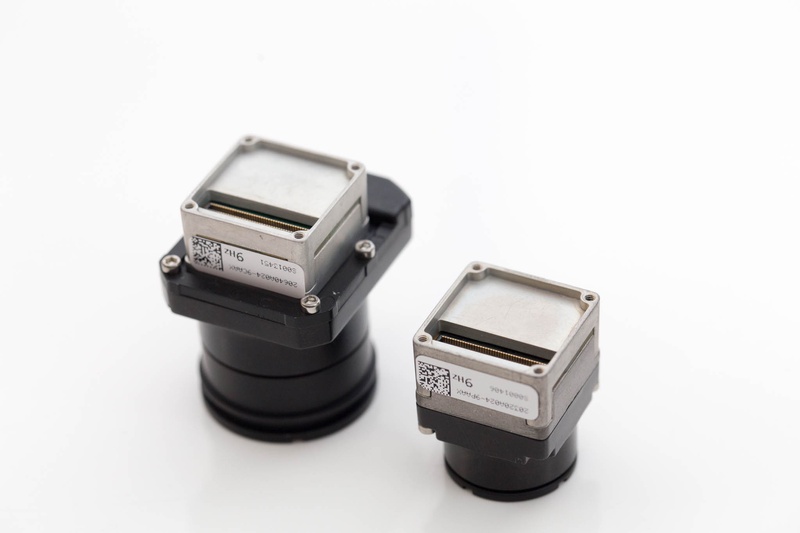
Design
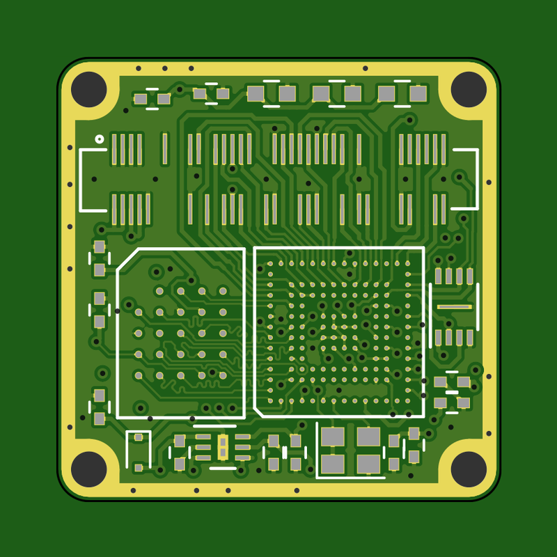
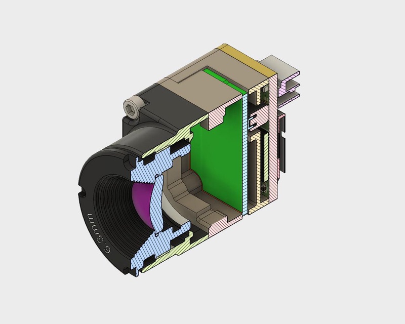
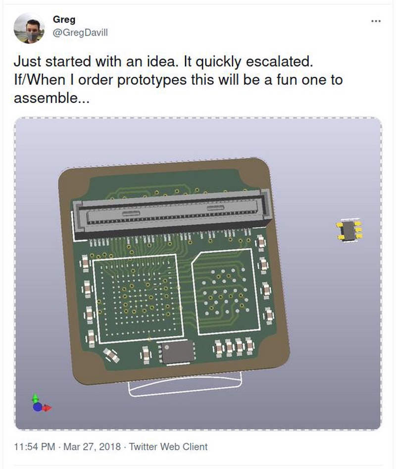
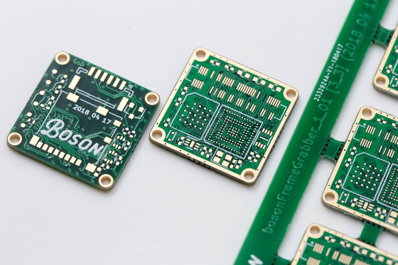
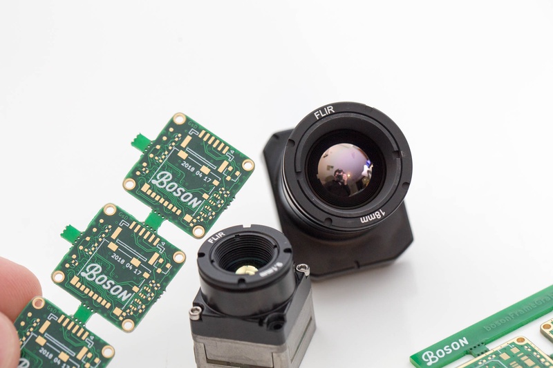
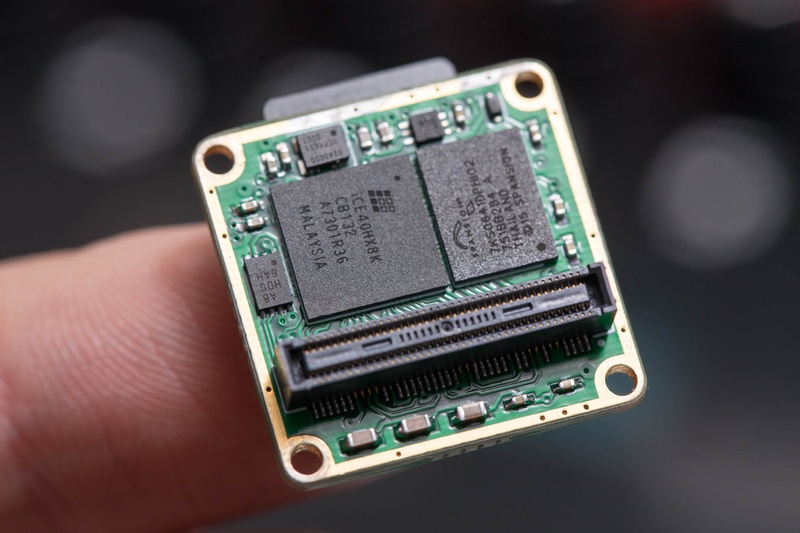
The design revolves around the two main ICs, the FPGA, and the HyperRAM. These were placed on the PCB behind the camera. The connector for the camera with the same custom footprint enabled all the camera signals to be routed out on a single layer, the use of an FPGA also helped here, as most of the time you can simply swap pins to help with routing.
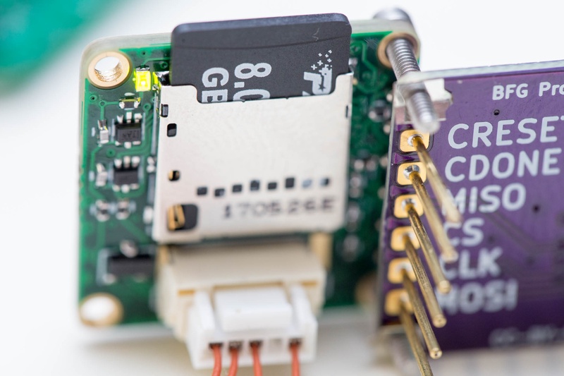
The FPGA is now responsible for handling the SD logic, I routed the signals required for 4bit SD mode, this can also be used in SPI mode by the FPGA. Starting with SPI mode should make this easier to bring up the firmware.
The device features 2 user I/O. these run through a bidirectional level converter, and TVS. My thoughts here is that this will make the I/O much more robust as the level converters I’m using will easily handle input voltages of 6-7V without complaint, the same can not be said for the FPGA.
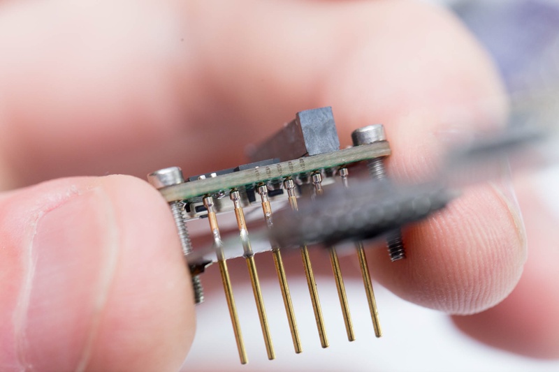
The RAM used here is the same HyperRAM as v1 prototype. 64Mbit DRAM with a 12pin HyperBus interface. I used a tiny 8Mbit QSPI Flash in 8 pin 2x3 USON package. and a JTAG interface on the back of the device which makes use of pogopins.
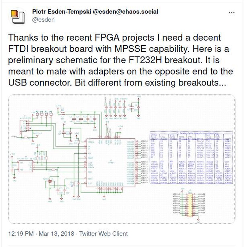
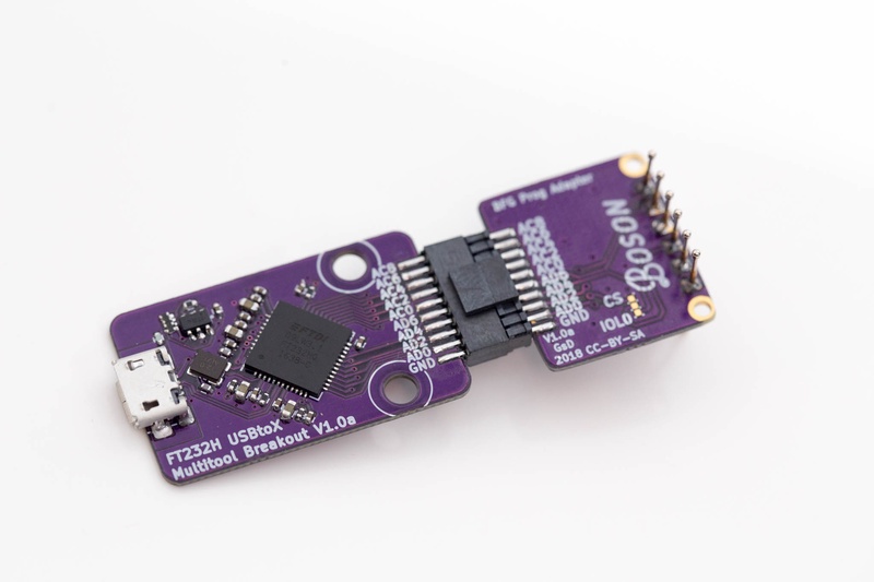
FT232H programmer
Hardware
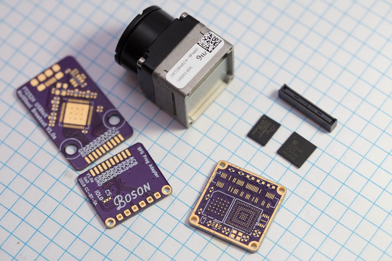
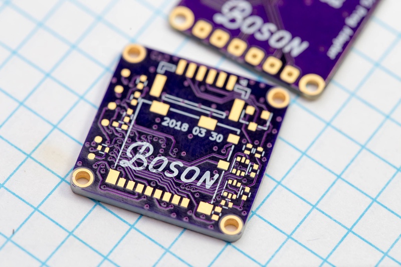
PCBs arrived from OSHPark. I haven’t used OSHPark for PCBs since it was Laen’s group PCB. (and the boards were still blue. :S ). But they are great quality, which should be expected. I ordered both the FT232H multitool design, a pogopin breakout, and my new Boson Frame Grabber PCB.
I had ordered a PCB from OSHPark before I discovered the hyperRAM footprint error on my last PCB, so unfortunately the main PCB was useless (what are you gonna do). I was able to use the programmer, and I used the PCB for BGA practice! (I shorted a few pins on this attempt, so well worth it). Speaking of OSHPark PCBs damn do they look nice! That LPI silkscreen process really shines!
Hardware Take 2
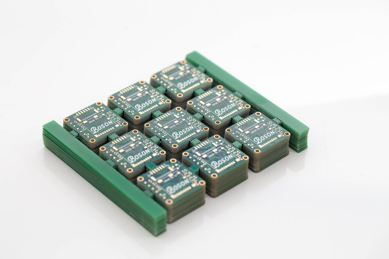
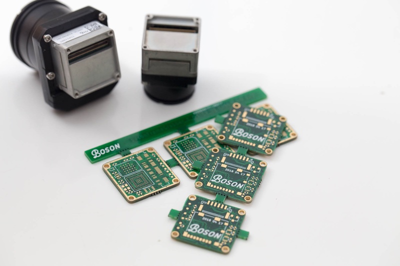
I had already ordered some new PCBs from JLCPCB.com after correcting the footprint of the HyperRAM. These boards showed up within about a week of ordering, this is of course using DHL (Otherwise your PCBs typically spend a few weeks in the mail system).
The PCBs from JLCPCB look great! this was the first time I used their service. Their manufacturing specs are very impressive for the price! I’ll definitely be using their service again! Although this is only a prototype run, given the size of my PCBs I decided to create a small panel using the GerberPanelizer tool (http://blog.thisisnotrocketscience.nl/projects/pcb-panelizer/)
This worked out great! JLCPCB did not have any issue routing out the space between boards. (I kept around 2mm between PCBs.)
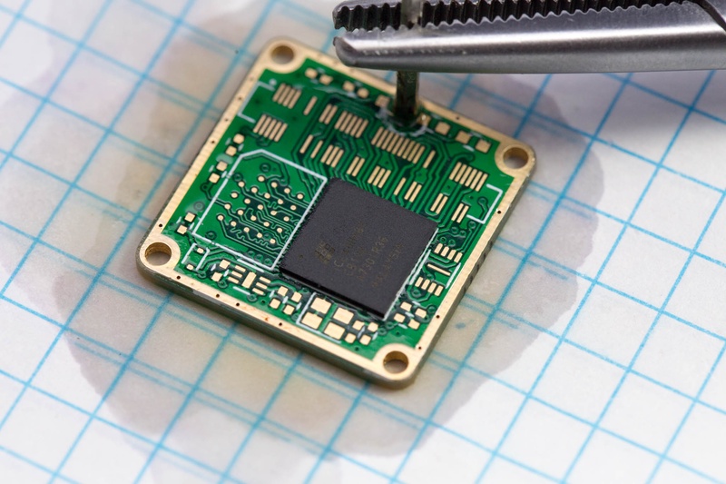
I soldered up a single PCB by hand, this is time consuming, but forces you to relax. (If you’re not relaxed while placing small parts with tweezers they tend to fling out and shoot across the room :S ). Again hot-air and flux. You can never have too much flux, I use AMTECH NC-559-V2-TF that I buy in large 30cc tubes that you can pickup from Louis Rossmann.
After assembly I really didn’t expect it to work, this is the first time I’ve soldered a 0.5mm BGA by hand, and you can’t be sure that it’s correctly soldered unless you use expensive x-ray inspection tools, or destructive methods (that would destroy your prototype). I connected up my homemade programmer and powered on the board with 3.3V from my bench power supply. It worked!
A little verilog code later, tinkering with examples found online I managed to have a compiled bitstream that would flash a LED. The LED started flashing. ^_^
The LED blinks? Now what?
Part 3 will take a look a the verilog and firmware required to get this thing up and running. Check it out here