Overview
I’ve been adding various “smart” devices to my home to control with automation via home assistant. Initially this was just dimmable and hue adjustable lighting, and then WiFi enabled switches to connect up the physical switch plates around the house as inputs into home assistant. And now I also have solar and power monitoring connected up into home assistant too.
I’ve wanted to add control and monitoring of my reverse cycle air conditioner into home assistant too. This would enable a skew of extra features that the default control panel and interface lack.
- Easily setting one-off timers
- Controlling the unit from the couch/bed
- Smart thermostat ranges where the unit only runs when solar is available
- Turning the unit off when I leave or enter
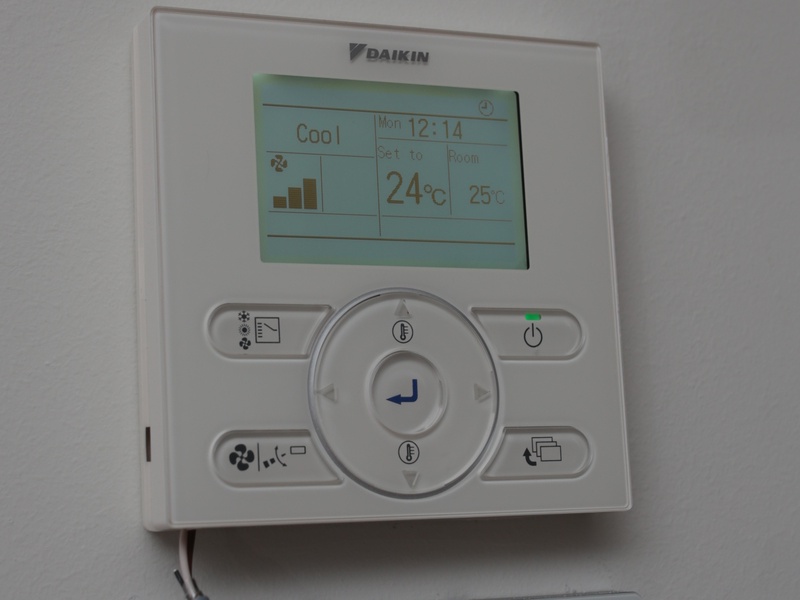
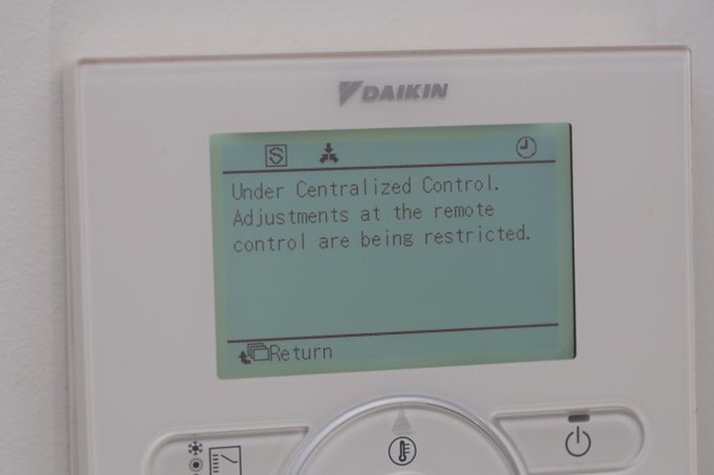
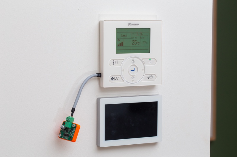
The A/C unit in question is a ducted reverse cycle air conditioner from Daikin. It features a ceiling unit which serves as an air intake, this runs through a heat exchanger and is ducted out to various rooms. The ceiling unit uses refrigerant lines connected to an outdoor unit. To form a heat pump. The system works in both a cooling or heating mode.
When adding devices to my smart home network I’m a bit particular. I try to ensure that devices are under local control not requiring an internet connection to perform their standard functions. I don’t want my lights to stop working because of an AWS outage. Or control of my air conditioner to stop because a manufacturer decides to turn off servers/services. This does limit my options, but is a strong driver for the choices in this project.
Adding automation
Off the shelf solutions to control split-systems do exist, however these typically rely on an IR control scheme. My unit does not have an IR controller, and instead uses a hardwired control panel on a wall that is connected into the ceiling unit. Daikin do provide a WiFi controller, It’s a little bit unclear if this does in-fact support my exact unit. This is a $200-300 device (without install fees) and from a bit of online research is only designed to be used with their phone App. Although there does appear to be a way to sync it with home assistant it rely on an internet connection.
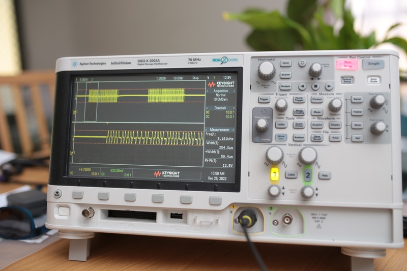
I became interested in the hard-wired connection between the ceiling unit and the wall controller. There are only 2 pins so it must carry power and modulated data on the single pair of wires. I pulled the controller off the wall, and using a multimeter I measured ~15V. I didn’t see any coupling to GND on each of the pins. So cautiously I hooked it upto my scope to take a peek at what might be going on, and saw something pretty cool! At regular interval there was an AC coupled alternating phase signal present.
I noticed on the back of the wall controller the wires connecting upto the ceiling were labelled P1/P2. So I googled P1P2 and came across an awesome project P1P2Serial. The P1P2Serial project had done what I was trying to do, and also had very good and clear documentation about the physical layer and protocol layer of the bus. I would urge anyone who is interested to dig into the resources available there to learn more. For completeness to this blog post I’m just skimming over the basics.
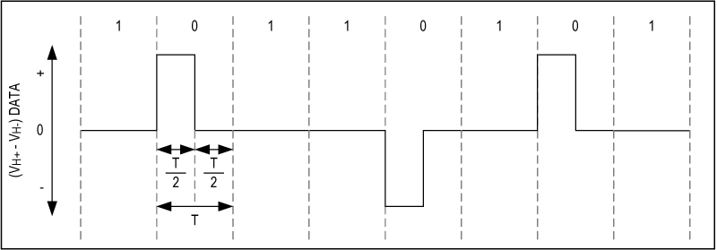
The Daikin controller has a MM1192 on the PCB, the datasheet for this part mentions it’s a “HBS-Compatible Driver and Receiver”, where HBS is short for “Home Bus Specification”. Maxim Semiconductor, now ADI has a compatible transceiver the MAX22088. There have a some App notes which go into detail about the physical layer.
- Standard 9600bps UART framing with even parity
- For a LOW in the UART byte, a half-bitwidth pulse is created, this alternates in polarity
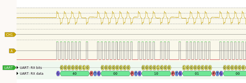
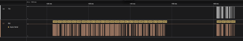
This provides enough info to start to attempt decoding. I took the data captured on my scope and imported it into pulseview. I AC coupled, took an absolute value then added a threshold to the signal to create a digital value. Then making use of pulseviews decoders I added a UART decoder. Recall that each UART bit is actually split in half, so I configured the UART decoder slightly fast, 9800bps, to ensure that it sampled in that first 1/2 bit, and not the LOW from the previous bit.
The decode worked and the bytes parity checks were coming back good.
This is where the Daikin system stops making use of homebus specification and their defined protocol layer, and implements their own protocol. Circling back to P1P2Serial, they’ve documented the protocol layer
Each packet is 4 bytes to 24 bytes in length and consists of the following:
| Byte | Description | Values |
|---|---|---|
| 0 | direction | 00h = request from main controller to peripheral 40h = response from peripheral |
| 1 | peripheral address | 00h = heat pump Fxh = external controller |
| 2 | packet type | 1Xh = packets in basic communication with heat pump 3Xh = packets from/to auxiliary controller(s) 0xh, 2xh, 60h-BFh = various parameter/status communication and settings |
| n | payload data | Packet type specific data, up to 20 bytes |
| 3 + n | CRC checksum |
Looking at the decoded scope trace from earlier:
- dir: 40h Response from peripheral
- adr: 00h Heat pump
- type: 10h Basic communications
First PCB
Following my project naming scheme I opened up project codename and after a few clicks got “Sapphire Captain” as a project name from this project. The goal was to make use of the MM1192 transceiver with an ESP32C3 to create a standalone bus powered PCB. I had just started playing around with ESPHome as a way to easily create home assistant compatible LED strip controllers. I knew it was possible to create custom C++ components in ESPHome. So my plan was to make use of the ESP32C3’s RMT peripheral to capture and transmit the physical layer. And then write a small driver to implement enough protocol layer to marshal commands/status between the Daikin and home assistant.
Unfortunately, having not used homebus or the MM1192 before my implementation of extracting power off the bus did not work. Due to this the project lay dormant for a few more months.
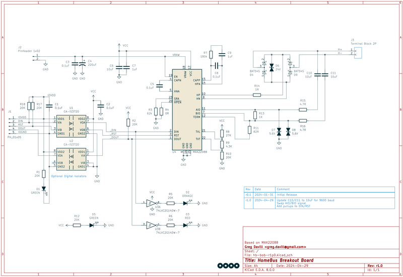
Second PCB
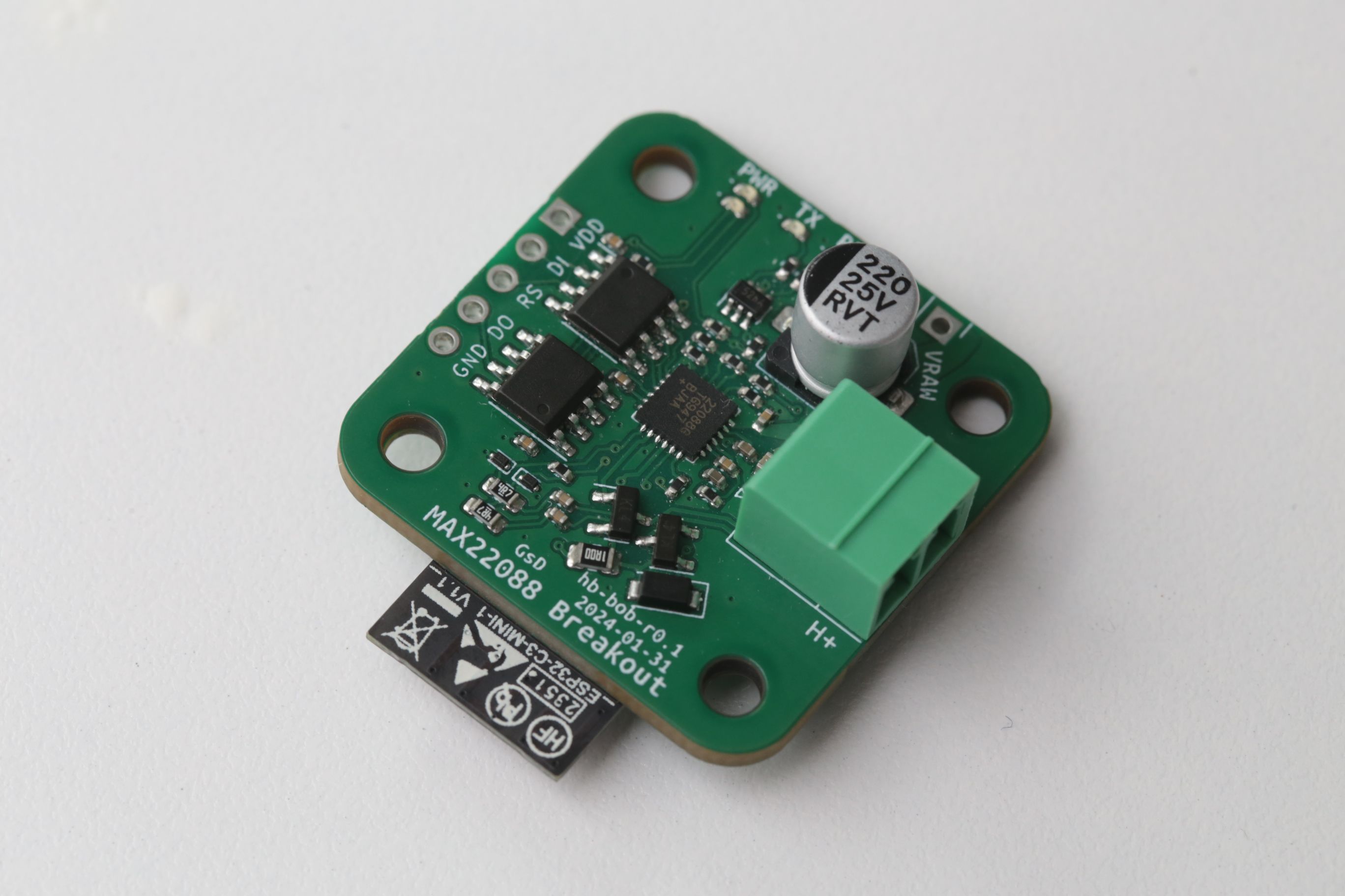
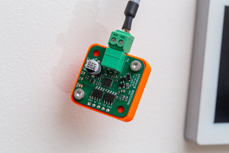
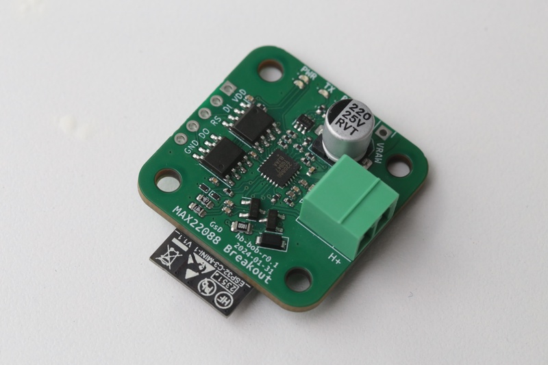
When I finally picked up the project again I decided to make use of the MAX22088, it is a more expensive part, however it details exactly how to design a bus powered device with reference schematics. So I designed up a small board to be powered off the P1P2 bus, provide the raw voltage output, and then an isolated Tx/Rx connection so I could comfortably leave this hooked up to my A/C while also connected to my laptop, and be confident nothing would fry.
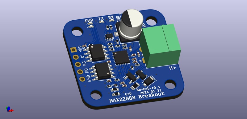
This was actually the first time I made use of JLCs PCBA assembly service. I ordered 5 assembled PCBs with DHL ended up around US$110. Not bad for a one off prototype design, if I’d have to buy a stencil, excess components, I’d end up at a similar cost.
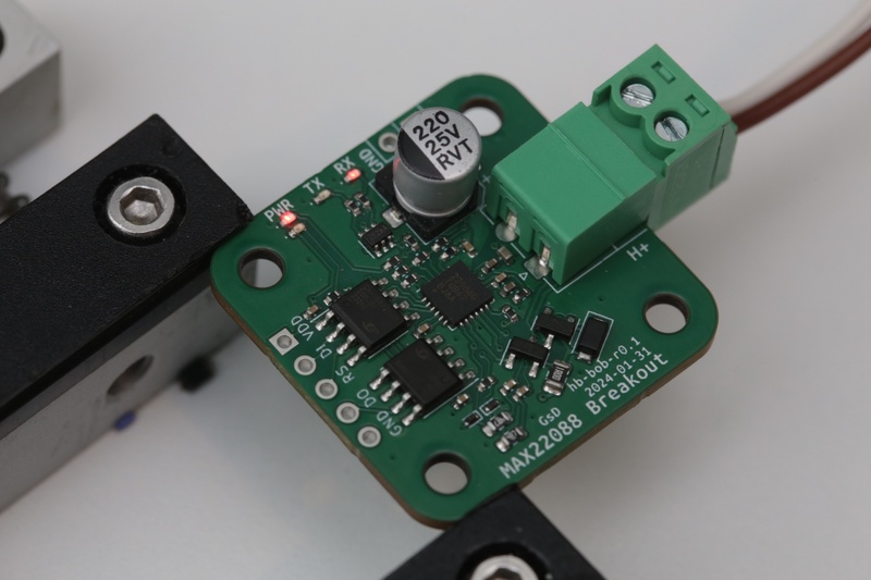
With the boards in hand I plugged them in and boom immediately started getting regular blinking lights on the RX LED I’d placed on the board! Hooking up my saleae logic analyser I could see reasonable looking signals coming from the board. Now I could dive into the firmware to work on interpreting the packets and responding.
I had looked through the code on P1P2Serial, which was mostly for different models of Daikins, and tried to implement it in an ESP32-IDF based project. After I’d adjusted some AC coupling caps on my MAX22088 board to handle the 9600bps signaling. It seemed like the Daikin was seeing my messages. I could turn the unit ON/OFF with a physical button on the ESP32 board. But it would lock out the main control panel.
After reading through the P1P2Serial code a bit more I noticed they detect a header of [00h, F0h, 30h] message as an Auxiliary controller status, and reply to it with an zero length payload acknowledgement [40h, F0h, 30h, 6Dh]. After issuing this, a few additional messages to us (F0h) started being sent! Nice.
Once some additional messages are acknowledged, message 38h is sent on each message cycle. Which is ~300ms or longer depending on number of messages in the current cycle. 38h is referred to as “FXMQ control” in P1P2, and appears as the primary mechanism an auxillary controller talks to the main controller.
The main controller sends the message to us, which contains the current status and control parameters. In our reply we are able to set new control values, (operating mode, target temperature, etc). Since Daikin doesn’t provide documentation for these low-level messages some bits are still unknown in function.
My ESPHome code fills out the payload like so:
if (buffer[0] == 0x00 && buffer[1] == 0xF0)
{
    const uint8_t *payload = &buffer[3];
    switch (buffer[2]) {

        case 0x38: {
          ESP_LOGI(TAG, "FXMQ control message (0x38)");

          uint8_t ping_response[] = {
              0x40, 0xF0, 0x38,             // Header
              (uint8_t)(payload[0] & 0x01), // target status
              payload[2],                   // target operating mode
              payload[4],                   // target temperature_cooling
              0x00,
              payload[6],                   // target fan_speed
              0x00,
              payload[8],                   // target temperature_heating
              0x00,
              payload[10],                  // target heat_fan speed
              payload[11],                  // unknown
              0x00,
              0x00,
              0x00,
              payload[15],                  // C0, E0 when payload[0] set to 1
              0x00,
              0x00,
              0x00,
              0xFF                          // crc byte, gets calculated later
          };
          ...
ESPHome
I ported the RMT code over to ESPHome, this was a bit more trouble than expected since ESPHome makes use of IDF v4, I had used v5 for my initial code. Between versions the API for RMT has changed significantly. But with that change done in ESPHome I made use of the Climate component. This creates this interface in home assistant. There is a control function to implement, this enables home assistant to device control. When we have new sensor/status data to report, the climate class gives us sensors we can update and publish back to home assistant.
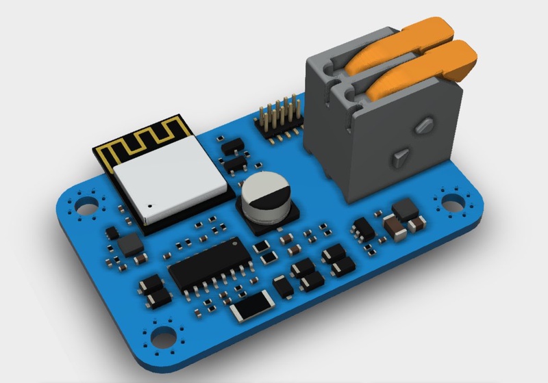
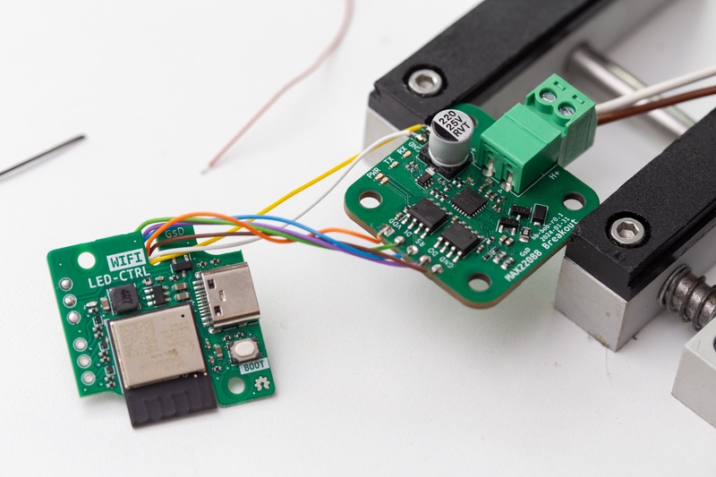
Up to this point I had a 10m cable routed from the wall controller around a hallway and into my electronics lab bench. This worked well for debugging and development. But it had been kept in this state for a few months. 🫣 To quickly neaten up the install I 3d printed a small enclosure and wired up the MAX22088 breakout board into an ESP32C3 board I developed for LED lighting. ESPHome provides an easy way to configure an OTA bootloader, and WiFi logging. So even through the board was not one my desk anymore I was still able to continue debugging and fixing higher-level protocol bugs with the firmware.
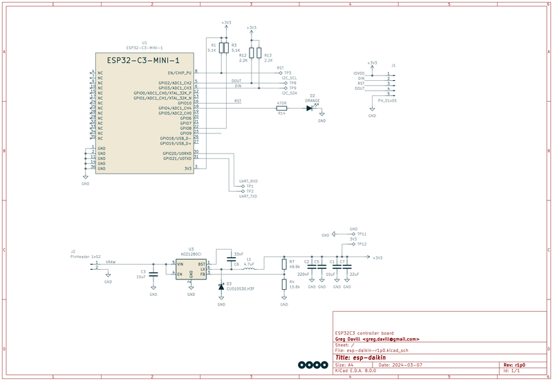
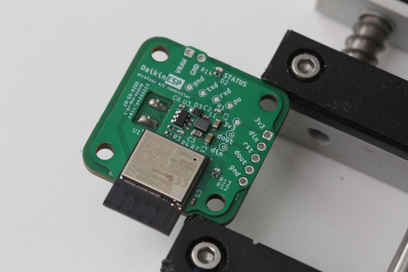
Custom ESP32 board
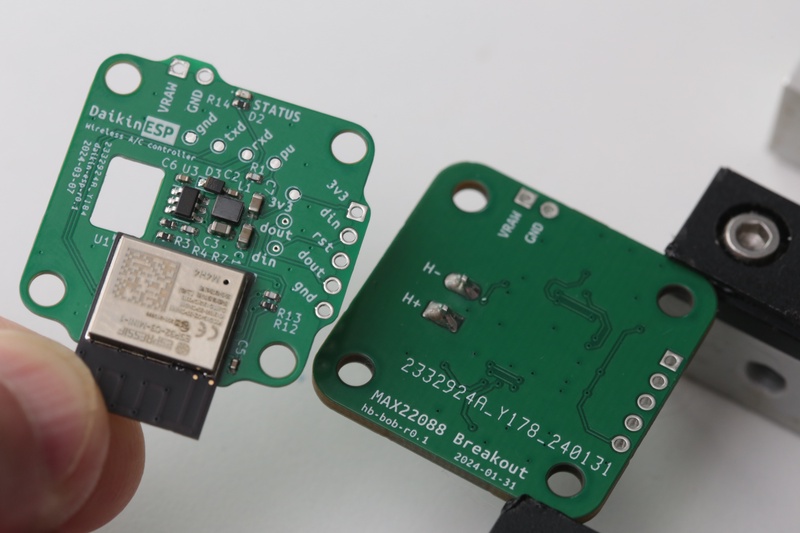
Having had 5 of the MAX22088 transceiver boards built I didn’t want them to go to waste when I created the final hardware for this project. So I developed a single layer ESP32C3 board that could be mounted to the back of the MAX22088 boards. If I didn’t have this requirement these two circuits could easily have been routed onto the one PCB.
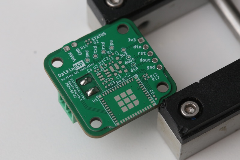
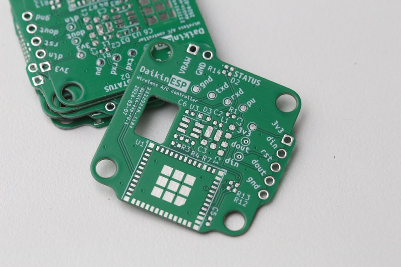
The circuit is just an ESP32C3, and a DCDC step down circuit to provide a 3v3 rail. and a single LED. I purposefully avoided a USB connector on this board opting for a slimmer design, my plan was to use the UART bootloader to load an initial firmware image, then exclusively use OTA. Hardware designers who make heavy use of the ESP might notice that I didn’t bring out GPIO9 to a test-point. This is a strapping pin and needed to enter USB/UART boot. -_-
Due to the LGA style of the ESP32C3 module it’s not super easy to access the GPIO9 pin. Since I only needed to access it once, I tried to avoid reflowing and reworking in a proper test-point. Instead I used an alligator clip to ground my scalpel blade, and with some careful positioning and wiggling managed to wedge it under the ESP module and make contact with the GPIO pin.
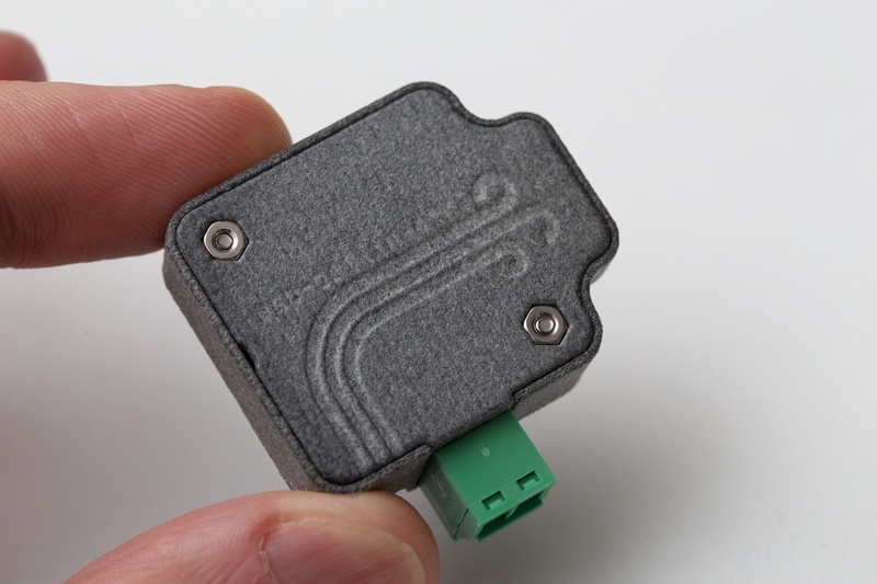
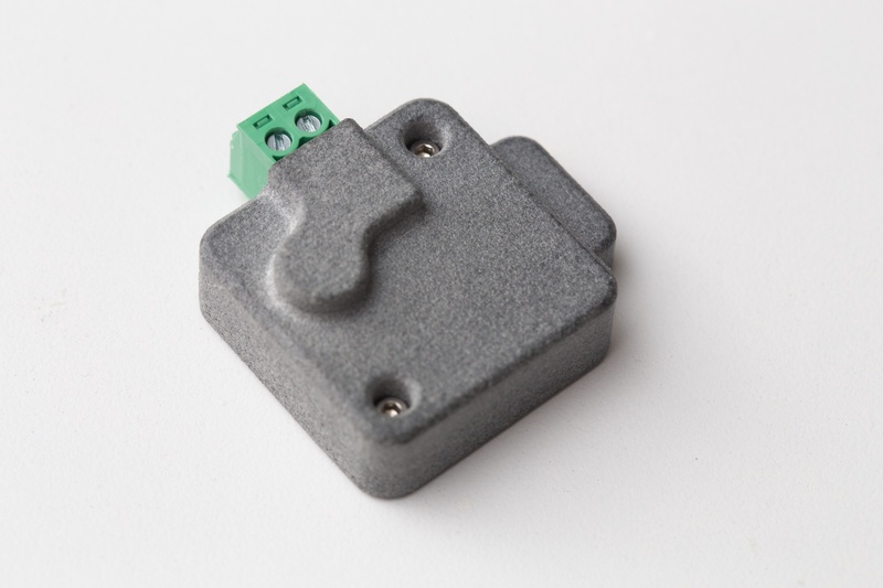
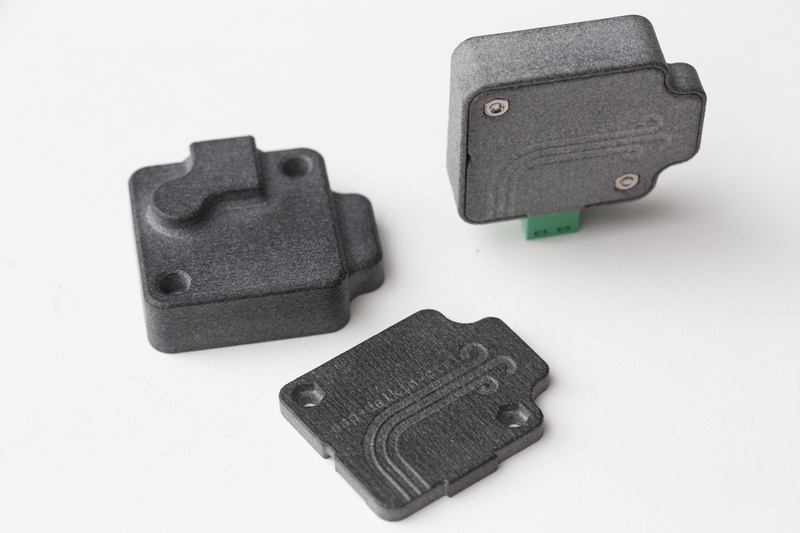
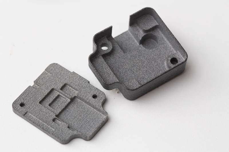
A custom designed 3d printed enclosure was designed to cover the entire module. I made use of Autodesk Fusion for the design, importing the PCB solid models and forming an enclosure around them. The enclosure is 2 pieces and fits together securely with M2.5 screws.
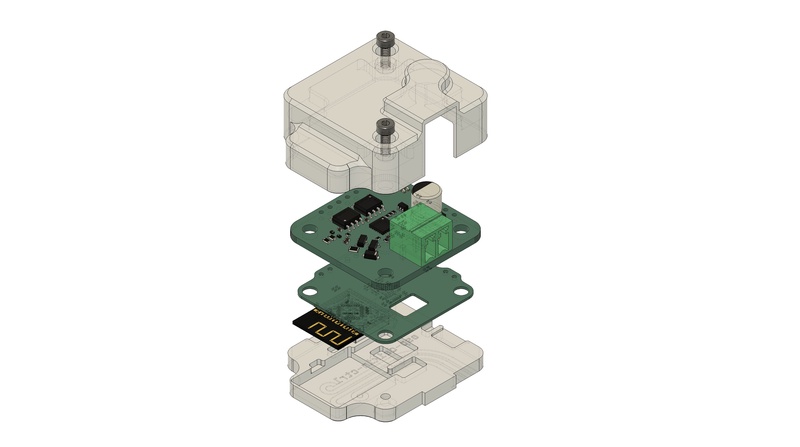
The finished enclosure turned out great printed in a MJF Nylon material offered by JLC.
HomeKit integration
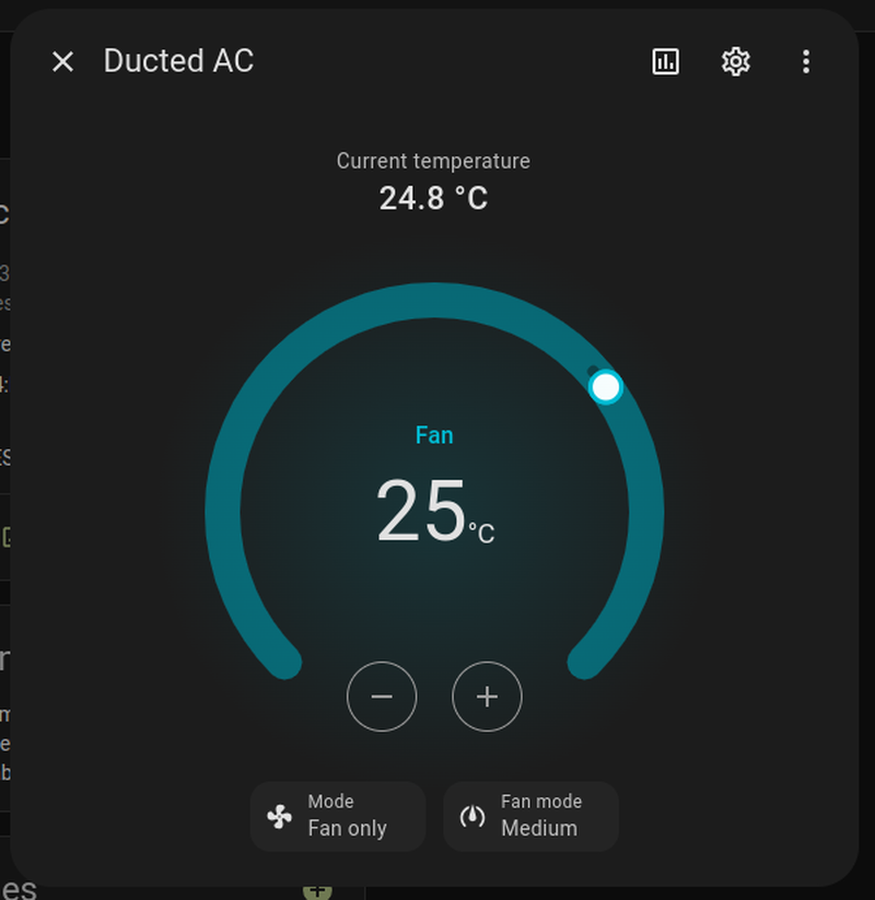
Home assistant has a great integration to behave like an Apple HomeKit Hub, this enables control of the devices from Apple Home, which is tightly integrated into iOS and MacOS. This meant that after getting the A/C working with Home assistant it just also works with Apple Home. This worked very well for Heat/Cool/Auto modes of the unit, but there was no control over the Fan Only mode.
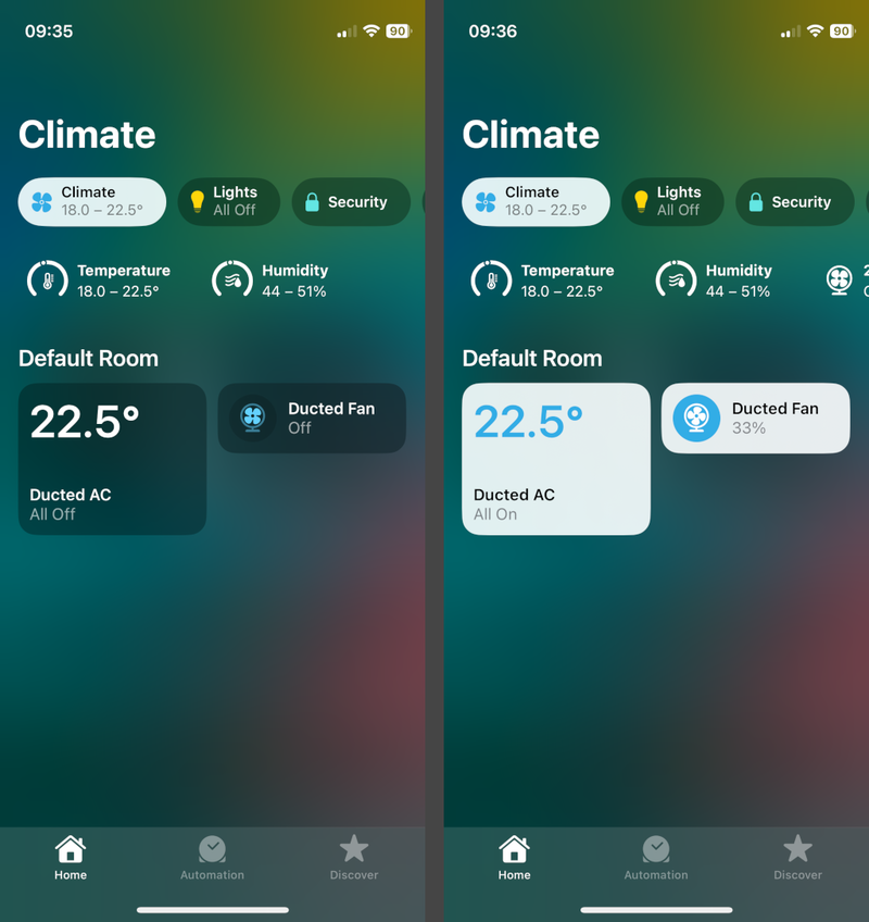
The Fan Only mode, circulates air throughout the house, but doesn’t active the heat pump. So it is very energy efficient. It was desirable to add control of this feature, after a little bit of research through ESPHome docs I found templates should help me achieve this goal. By defining a template fan, we can expose a fan controller to Apple, and when we receive control messages we can re-route them to control the A/C instead.
This is the configuration I added
climate:
  - platform: daikin_ducted
    id: daikin0
    name: "Ducted AC"
    on_state:
      then:
        lambda: |-
          auto call = id(templatefan0).make_call();
          call.set_state(x.mode == climate::CLIMATE_MODE_FAN_ONLY);

          if(x.fan_mode == climate::CLIMATE_FAN_LOW)
            call.set_speed(1);
          else if(x.fan_mode == climate::CLIMATE_FAN_MEDIUM)
            call.set_speed(2);
          else if(x.fan_mode == climate::CLIMATE_FAN_HIGH)
            call.set_speed(3);

          if(  id(templatefan0).speed != call.get_speed()
            || id(templatefan0).state != call.get_state())
            call.perform();

fan:
  - platform: template
    name: "Ducted Fan"
    id: templatefan0
    speed_count: 3
    on_state:
      then:
        lambda: |-
          auto call = id(daikin0).make_call();
          call.set_mode(x->state ? "FAN_ONLY" : "OFF");

          if(id(daikin0).mode != call.get_mode())
            call.perform();
    on_speed_set:
      then:
        lambda: |-
          auto call = id(daikin0).make_call();
          switch(x) {
            case 1: call.set_fan_mode("LOW"); break;
            case 2: call.set_fan_mode("MEDIUM"); break;
            case 3: call.set_fan_mode("HIGH"); break;
            default: break;
          }

          if(id(daikin0).fan_mode != call.get_fan_mode())
            call.perform();
The lambdas contain C++ snippets which marshal across the FAN_ONLY control of the A/C to and from the template fan. Care is needed to check and only perform the call() action on new data. Otherwise a loop is formed where each devices on_state lambda calls the other on_state lambda.
With this extra yaml code in place, an extra fan device appears in the Apple Home app. It shows the status if the A/C in fan only mode, and enables control from iOS.
IDF bugs
The system has been working great for a few months on the custom hardware, hidden away in the wall. However when adding the new fan only features I noticed that the firmware was reporting a CRC error on a specific message, I added some extra debugging messages to get a bit more insight into the issue. Every 5 minutes the main controller sends a request for the heat-pumps name (message type A1h). When the heat pump responds the message the ESP tries to decode ends up corrupted.
[10:16:19][VV][homebus:217][rmt_rx]: rx: (len=768, buffer=0x3fc99358)
[10:16:19][VV][homebus:088][rmt_rx]: l=20 [00 00 a1 00 00 00 00 00 00 00 00 00 00 00 00 00 00 00 00 45]
[10:16:19][VV][homebus:217][rmt_rx]: rx: (len=1016, buffer=0x3fc99098)
[10:16:19][VV][homebus:088][rmt_rx]: l=30 [00 00 00 00 00 00 00 00 00 45 40 00 a1 00 52 5a 51 31 30 30 4c 56 31 00 00 00 00 00 00 58]
[10:16:19][E][daikin_ducted.climate:062][rmt_rx]: Packet CRC error 58 != 3f (length = 30)
[10:16:19][VV][esp-idf:000][rmt_rx]: I (300093) daikin_ducted.climate: 0x3fca4070   00 00 00 00 00 00 00 00  00 45 40 00 a1 00 52 5a  |.........E@...RZ|

[10:16:19][VV][esp-idf:000][rmt_rx]: I (300096) daikin_ducted.climate: 0x3fca4080   51 31 30 30 4c 56 31 00  00 00 00 00 00 58 00 00  |Q100LV1......X..|

[10:16:19][VV][homebus:217][rmt_rx]: rx: (len=736, buffer=0x3fc99498)
[10:16:19][VV][homebus:088][rmt_rx]: l=23 [00 f0 35 52 5a 51 31 30 30 4c 56 31 00 00 00 00 00 00 00 00 00 00 67]
[10:16:19][I][daikin_ducted.climate:317][rmt_rx]: Outside Name(0x35): RZQ100LV1
The message is not directed at us, so it’s not actually essential that we decode it, but I still wanted to work out the issue, and fix it. Incase it caused issues with other messages that we do need to handle. To provide a bit more info for debugging I took the controller out of the wall and hooked up the saleae again, and took a capture alongside the log recorded by the ESP.
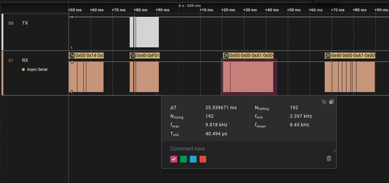
This capture confirmed the messages were transmitted correctly over the bus, so the issue is on the ESP side.
Actual messages on bus:
[00 00 a1 00 00 00 00 00 00 00 00 00 00 00 00 00 00 00 00 45]
[40 00 a1 00 52 5a 51 31 30 30 4c 56 31 00 00 00 00 00 00 58]
The RMT peripheral in the ESP is what I’m using to capture the bus. It combines a counter and edge detection to store timestamps of high/low transitions. This takes a large ISR overhead off the processor, by configuring a timeout value you can receive an interrupt while mid-packet if the buffers fill, or at the end of a packet. Here is a diagram from the ESP32C3 reference manual describing the peripheral.
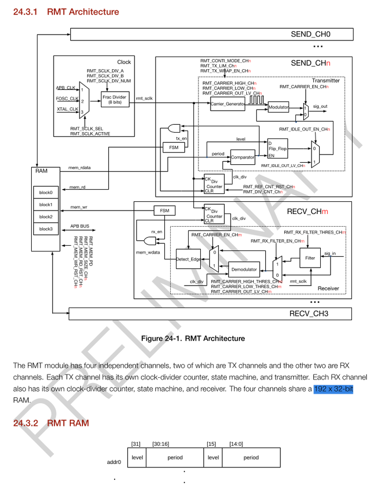
Note that the RAM for the peripheral is dedicated and listed as 192 * 32bit. This is split into 4 blocks each 48 * 32bits in size. Each 32bit word stores 2 transitions/periods. So in a single block of RMT RAM we can save 96 edges of data, before an interrupt routine needs to take over and empty that data. The ESP-IDF driver for RMT takes care of this step for us. The transitions are stored in a system memory buffer that is passed to our application only once a timeout event happens.
This took me a few hours to figure out, but keen eyed readers might have started to piece together the issue. In my extra debugging info listed above I record the length and buffer address of the raw RMT data before processing. The first buffer is 768 bytes in length. This is 384 edges; 192 falling, and 192 rising. This means the packet is an exact multiple of the RMT RAM blocks. Two more pieces of the puzzle:
- On a timeout, the RMT peripheral inserts an entry with a period of 0 to indicate the end of an RMT packet into it’s RAM.
- In ESP-IDF v4.4.8, the RMT driver interrupt processes the timeout flag before the buffer threshold flag.
Have you worked out the bug with these clues?
In my case I’ve configured the RX2 channel to make use of 2 RAM blocks, the driver configures the RMT_CH2_RX_LIM_REG to 48 (one RAM block) in this case. Consider what happens if a RMT RAM block is filled with data, but hasn’t rolled over the RMT_CH2_RX_LIM_REG yet, so a RXT_CH2_RX_THR_EVENT_INT hasn’t occurred, but will occur if another edge is seen. We’re at the end of a packet, so not more edge will be seen. The hardware detects a timeout, so inserts a 0 period into the buffer. This simultaneously produces a RXT_CH2_RX_THR_EVENT_INT and RMT_CH2_RX_END_INT.
1. The drivers interrupt handler runs and sees the `RMT_CH2_RX_END_INT` status so it handles that and passes data to our application, which results in this buffer.
[00 00 a1 00 00 00 00 00 00 00 00 00 00 00 00 00 00 00 00 45]

2. It continues through the interrupt routine and starts processing the `RXT_CH2_RX_THR_EVENT_INT` interrupt.
   48 words of RMT data is stored in the driver SRAM buffer
[00 00 00 00 00 00 00 00 00 45 ...

3. The next packet arrives and is appended to the erroneous data left over by the bug.
... 40 00 a1 00 52 5a 51 31 30 30 4c 56 31 00 00 00 00 00 00 58]
I’m currently stuck on IDF v4, as this is what ESPHome is still using, and per Espressif’s support terms they ceased bugfix releases in July 2024 with the release of v4.4.8.
An easy fix for this is to clear the RXT_CH2_RX_THR_EVENT_INT status if we handle a RMT_CH2_RX_END_INT even in the same interrupt routine. However since bugfixes in the SDK won’t be accepted now, I’ve implemented a fix that works in my use case at the application level.
rmt_item32_t *items = (rmt_item32_t *)xRingbufferReceive(rb, &length, portMAX_DELAY);

// ESP-IDF bug, if rx_end completes on a rx_lim boundary, writing of an rx_end marker
// triggers the rx_thresh interrupt and affixes the end of this packet to the start of the next.
// Can't be fixed in IDF as 4.4.8 isn't getting any additional bug fixes.
// As configured this boundary is 384 bytes. Re-starting the rmt_rx resets the buffer pointers.
if((length % 384) == 0){
    esp_err_t error = rmt_rx_start(RMT_CHANNEL_2, true);
    if (error != ESP_OK)
    {
    ESP_LOGE(TAG, "Restart of rmt_rx failed");
    }
}

if (items)
{
    // process RMT data
}
This is a pretty clean fix. This does create a period where packets may not be detected, but the Daikin protocol leaves 10-20ms between packets so this isn’t an issue in this case. And we now correctly receive packets that are a multiple of RMT RAM size!
[09:56:17][VV][homebus:217][rmt_rx]: rx: (len=768, buffer=0x3fc99348)
[09:56:17][VV][homebus:088][rmt_rx]: l=20 [00 00 a1 00 00 00 00 00 00 00 00 00 00 00 00 00 00 00 00 45]
[09:56:17][VV][homebus:217][rmt_rx]: rx: (len=632, buffer=0x3fc99098)
[09:56:17][VV][homebus:088][rmt_rx]: l=20 [40 00 a1 00 52 5a 51 31 30 30 4c 56 31 00 00 00 00 00 00 58]
[09:56:17][VV][homebus:217][rmt_rx]: rx: (len=736, buffer=0x3fc99318)
[09:56:17][VV][homebus:088][rmt_rx]: l=23 [00 f0 35 52 5a 51 31 30 30 4c 56 31 00 00 00 00 00 00 00 00 00 00 67]
[09:56:17][I][daikin_ducted.climate:317][rmt_rx]: Outside Name(0x35): RZQ100LV1
Conclusion
Thanks for reading along with this journey. If you’re after an assembled device to control your A/C check out the hardware currently sold at the P1P2MQTT project, when I started the hardware wasn’t quite doing what I wanted, but it’s come a long way and would have just worked for my A/C.
Downloads
If you want to download the circuit designs or ESPHome firmware that I’ve created it’s open source licensed and available. I’d love to hear if you’re able to add some smarts to your ducted air conditioners. I’m not planning on selling assembled units of this design.